
Bespoke high-res PCB scanning
This post embeds images distributed in either WebP or JPEG XL formats, whichever your browser prefers to fetch. If it doesn't support either, a lower resolution PNG or JPEG 1992 file will be shown instead.
Digital microscopy is fun. Except when you have to deal with limited equipment, subpar lenses, etc.
But hey, one can still make do with what they have, right?
Prehistoric times
Back in mid-2023, I was working on a long-running project of creating a custom cartridge for the 3DS to act as a debug port for my (definitely fruitless) bare-metal OSdev hobby on that platform, as the console lacks any other exposed, easy-to-configure port that can send and receive digital data at useful speeds.
Part of that process obviously includes designing a custom PCB, which was only really my third use of KiCAD, or any eeCAD package for that matter1. And then you have to get it manufactured and populated; the former was done at that impossibly cheap Chinese PCB fab we in the hobby electronics business all know of, and the latter was done by hand with solder paste, without a stencil2, and my trusty MHP30 hot plate I had gottenimpulsively bought about a year earlier.
This was the first board where I had space constraints; one does not simply design a 27mm wide board3 without consideration for component size. Combine that with my subpar dexterity masterfully earning me last place on a human pick-and-place leaderboard, and you get bridged contacts galore. If only I could see my mistakes up close with more than a lousy inspection lens...
Enter Le Bon Coin, a French eBay or Craigslist of sorts. Plenty of great finds on there if you spend the time, and I search for anybody local selling a digital inspection microscope, and find what looks to be a decent one for around 140€. Not that I would know what a good microscope assembly looks like, this was to get my feet wet.
HDMI and USB UVC video feed output, good enough. Along with a swing arm and cheap LED ring light from AliExpress, safe to say it was enough for close inspection of my PCB; and helped me fix my soldering mistakes ever since. Later on I would go making my own bespoke light polariser setup to reduce glare as well as getting another better microscope assembly with configurable focus, but I will spare you the details.
What if you could, like, glue photos together?
I knew what microscope stitching was, but had no idea how to do it, or what software is available to do that. I did know how to use one particular stitching tool though, namely Hugin, in all its crashy, stale development, barely usable UI and horribly slow glory. Turns out, I'm not the first one to use Hugin for stitching microscope imagery, Derek D.V. Leung wrote a blog post about it; that post right there taught me how to use Hugin's advanced UI, and I never set foot back in the simplified UI since—that's how much more powerful it is.
Now, how to take a subject, put it under the the magic camera and lens assembly, and take roughly evenly spaced picures you ask? By hand, sliding a piece of paper the subject rest on, of course! Ghetto style. As for snapping the pictures, I use GNOME's Cheese app, simply because KDE's Kamoso refused to negotiate communication with the camera in the proper format4. Prior to that unfortunately one needs to boot up a proper UVC camera configuration tool to change parameters such as disabling auto-exposure.
By trial, error, nudging, and an unhealthy amount of pressing the space bar, sets of mostly evenly spaced out JPEGs end up in my filesystem. Only two problems I keep running into is not having enough overlap between shots or missing sections entirely, usually around the subject's edges, but Hugin works reasonably well even in those circumstances, with some manual intervention for areas where its similarity matcher failed.
This is the point where I drop a high-res heads of a 1999 French one euro coin:

Getting long
Not only is the capture process manual and tedious, Hugin also has a problem with long subjects. I means specifically long, not large, as the latter implies great dimensions in both X and Y axes, areas where Hugin shines. The problems arises with thin items spanning ~50 photos on one axis but only 3 on the other, one of those being a flatbed scanner's sensor array I pulled from my since dead inkjet printer5. To hammer the nail in even further, the back side of such a sensor array PCB has many repetitive features, which makes sense because those are just light-sensitive shift registers, but Hugin's automatic control point detection thinks they're all next to each other.

Reaching the point of mostly straightness6 as pictured above was hours of trial and error, painstakingly removing mismatched control points that oh so happily threw off Hugin's iterative solver and collapsed the entire scan area into a singularity of distorted images.
Plus the areas missing a capture are pretty obvious, with dark spots due to vignetting Hugin can't compensate for the exponential lightness falloff of.
I needed a better system.
Ender 3's make for good parts, actually
The easiest way to fix the whole, you know, tedium and consistency issue is to simply motorise the setup. Move the camera assembly or move the subject, same deal, but moving the camera introduces all sorts of vibrations you have to wait to stop, and at lens FOVs of fractions of a degree, those do not stop for a long time.
How hard could getting a motorised stage be then? Professional ones cost tens of thousands. Cheap Chinese ones cost thousands.
Building my own out of linear rail stages? Even small ones cost upwards of 50€ for a single axis.
Building my own out of 2nd hand 3D printer parts? That's 50€ for the whole build, frame included!
Granted, the repeatability might not be as good as the professional stuff, but even cheap printers like the venerable Ender 3 have acceptable accuracy overall, lest its absence become very visible as the plastic extrusions would look wonky, exacerbated by their layered nature.
Now, I got very lucky. The 50€ Ender 3 I found on Le Bon Coin as well came fully upgraded with (admittely low quality) linear rails and dual Z motors, simplifying the design required to attach things to the linear motion system. Bit o' CAD based on the STEP model of the printer provided by Creality themselves, creating custom brackets for the 2 stepper motors as well as the Y axis, and I've got myself a printer that doesn't print but moves a plate along a plane:
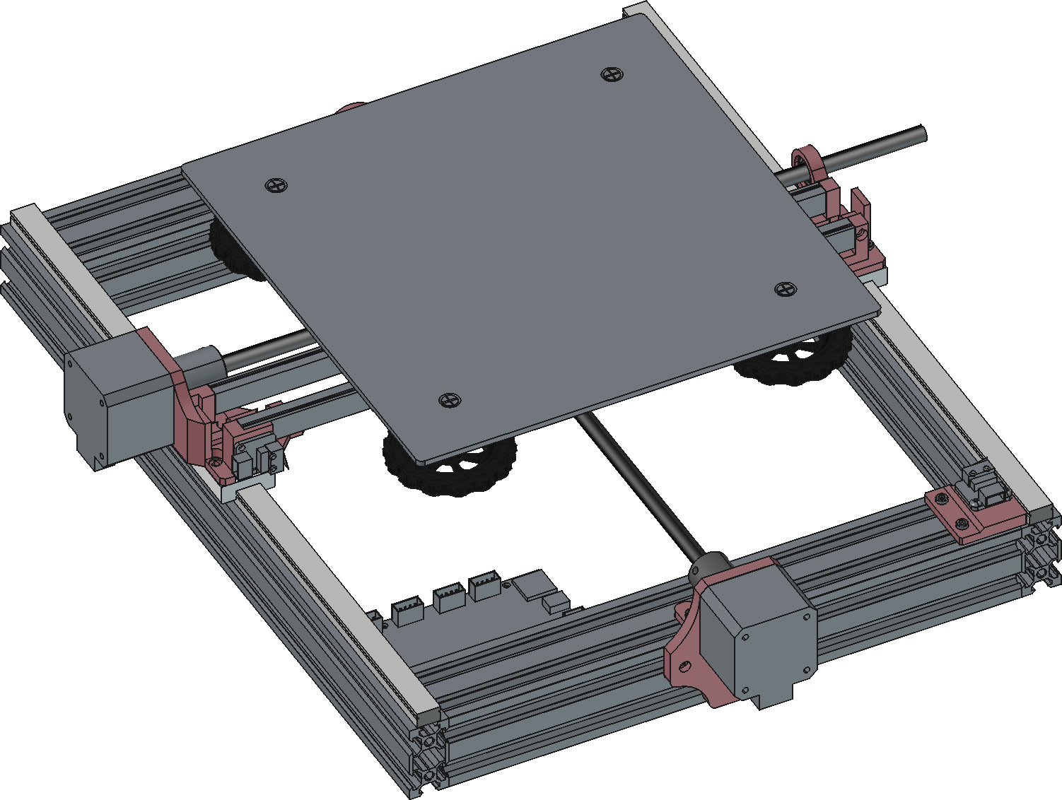
Reaching this state only took two iterations on the bracket parts to reach the desired rigidity. It's also, incidentally, the first time I used M4 threaded inserts (would've gone for M5 but didn't have any on hand) and used teardrop-shaped holes for bolts sitting horizontally—a technique I knew existed but never took the time to understand until I read Rahix's extensive article on designing for 3D printing through their FusedFilamentDesign addon for FreeCAD7.
Much ado about running GCode
As dingy as it is, I'm not throwing that Ender 3 control board away for something else I don't even have on hand right now. It's got enough power for the tiny accelerations and ridiculously low amount of force a motorised XY stage needs, and is one of the more recent STM32-based ones (shipped with version 4.2.7).
But the board still thinks it's controlling a 4-axis machine (X, Y, Z, and extruder) with motion capabilities, range, speeds and steps per revolution that don't match its new body. Oh no, I gave the printer gender dysphoria 😭
These boards, even the older 8-bit AVR revisions, run the increasingly deprecated Marlin Firmware. Changing any of its more static parameters like number of axes require recompiling from scratch as you change literal #defines applied to its entire codebase. Bit of an excruciating config system that, innit? At least they have decent documentation on what most options do8. In case you're interested, you can look at the Configuration.h I built it with.
Speaking without a cable
Let me tell ya, having a USB cable running from a PC to the board gets tiring real quick, even for testing. It so happens there's a flurry of inexpensive devices that can speak both Wi-Fi and UART serial at the same time, wow, can you believe it? Now if only I could make one of them relay commands over wireless and be plugged into the Ender 3 board 🤔
*Camera pans left, ESP3D enters the scene*
The good thing with hoarding swathes of inexpensive dev boards, in this case a WeMos D1 miniPro (running ESP8266), is that one day your unhealthy buying habits become useful. This is one such moment. If you've looked at the Configuration.h file above, you might have seen I've set the main serial communication to pins normally intended for the printer's LCD screen. Screens? Where we're going, we don't need screens. No, Marty, that's where the Wi-Fi module goes! Even provides power for the dang thing.
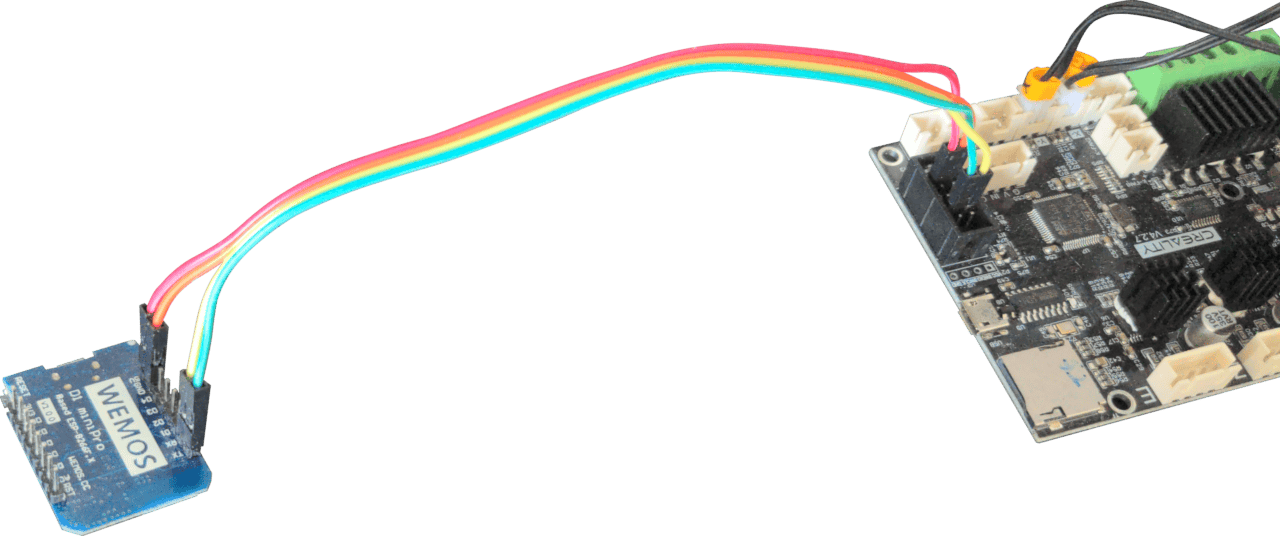
A machine has appeared into the real world
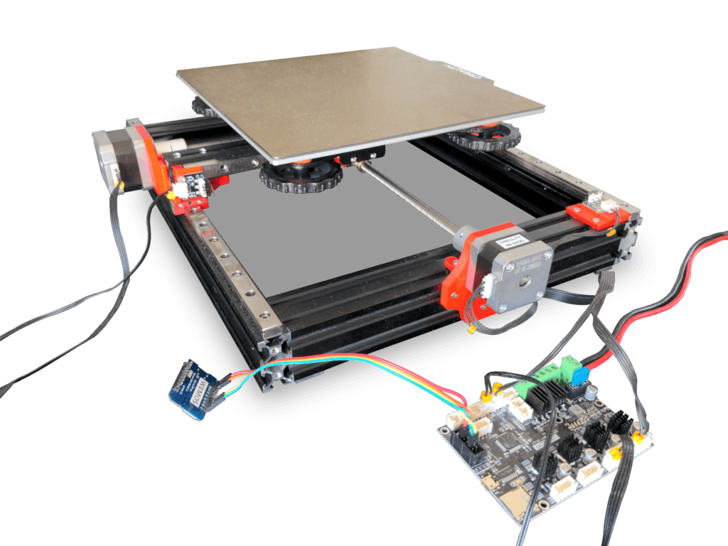
Finetuning
Now the thing works. Homing can complete without a hitch, the virtual end-stop at the end of travel works, steps per revolutions are configured correctly and 1 mm is, as best it can, 1 mm. But there's always a few things bugging you, no matter how much you improve the thing.
The first was how loud the stepper movement was, for something that has to exert no more torque than what's necessary to overcome friction in the nuts riding along the threaded rods. The particular Ender 3 board I have is marked with "TE", meaning the drivers are A4988, and those do not have Trinamic's StealthChop mode or equivalent. Even if I had TMC drivers, the lack of UART communication between the microcontroller and the drivers means I couldn't enable it anyway. Only option, and a reasonable one at that, is to turn down the current adjustment knob to limit how hard the steppers are driven to just enough amps for the gantry to move, but not be able to move e.g. my water bottle out of the way if it tries. I don't want this thing destroying itself because of my stupidity.
The second was backlash: the nuts riding the threaded rods are normally used on the printer's Z axis, a realm where gravity pulls things down no matter what, meaning backlash is functionally not an issue. These now sit on the horizontal plane and have about one and a half motor step's worth of non-movement when reversing direction. Needless to say it's unacceptable for something that needs to move with sub-millimetre accuracy for microscopy purposes. Oh yeah, remember that's the point of all of this? Nothing a few of AliExpress' finest mid quality anti-backlash nuts can't fix.
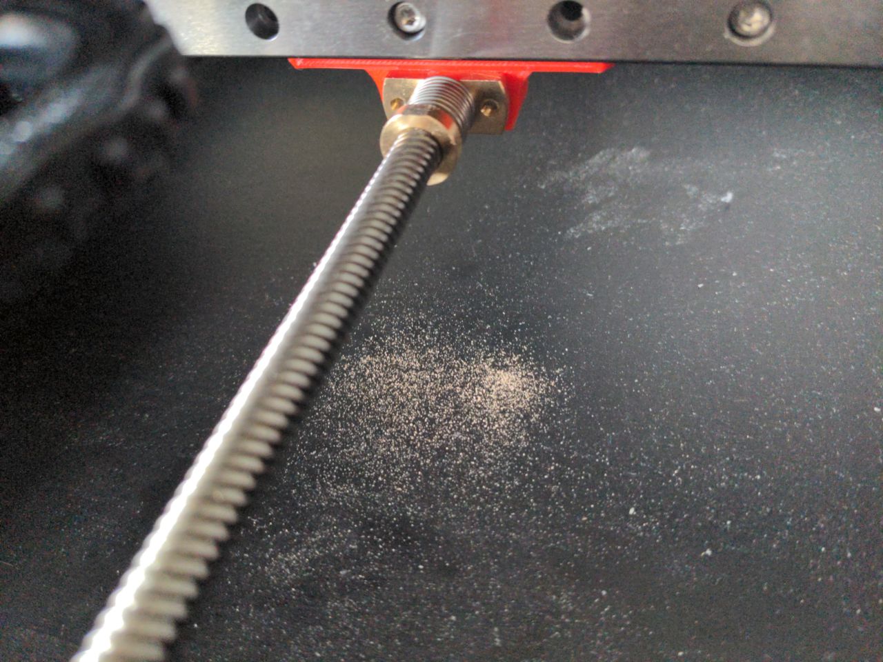
Did I mention files are useful tools to have?
Moovin' schmoovin'
That's a nice fancy mechanised table. A shame it's useless right now.
The future might see me make a properly designed native (probably C++ because OpenCV) application to run the stage and microscope assembly in tandem, but until further notice we live in the present, and it's 33°C inside, brain no worky. Python time.
I slapped together some whack-job code with requests to send the motorised stage commands over HTTP, and linuxpy to interface with the video feed the microscope exposes over USB and Linux turns into a V4L2 device. While making the path planner I added the ability to output its generated path to SVG:

Implementation was otherwise smooth sailing. I ask the microscope to send an MJPEG stream, meaning one can just capture the raw frame data and save it to disk as they're normal JPEG files. One hitch was frame latency, as the stream isn't being read from while moving and a few frames are buffered in flight, reading video at each stop point on the path resulted in data from past points being shown instead. Just discard some frames before saving.
Stinkin' stitchin'
Now you end up with this mess:
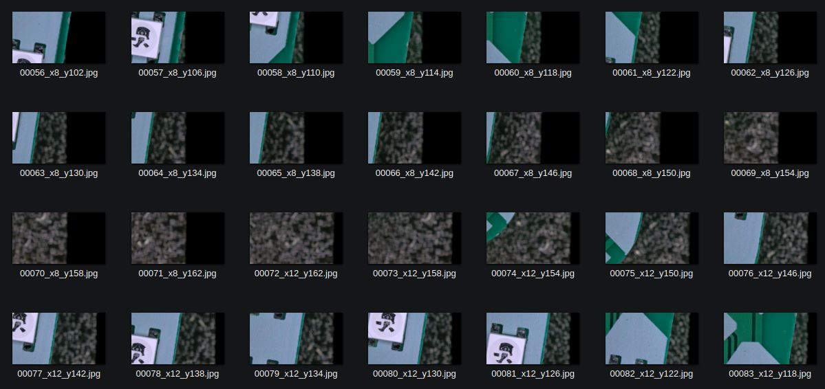
Not much different from what I did by hand, you might say. You would be correct except for one small detail: there are 10 times more files now.
You can try to feed this into Hugin all you want, if the minute-long UI freeze when merely importing them to the list of images doesn't deter you, doing a linear automatic control point detection9 might fool you into thinking it just might work. Too bad, trying to run even a single iteration of the position solver will freeze the software with no hope of recovery. Won't even hog a CPU core in the process, it will just be lost waiting on its mysterious pre-processing steps until you grant it the sweet mercy of a kill -9.
It's all the fault of the US government
There are... not that many options for stitching sets of microscope images out there. Even less so that are open source. Despite this, a specific algorithm, or its implementation thereof, keeps coming back: MIST, developed by the United States' NIST, with an N10. It has a Java and Python implementation; I picked the Java one in the hopes of overall better performance, which comes as a plugin for ImageJ11.
Overall it works, fairly well given it doesn't require much extra data to start working; only the grid size and scan pattern. But don't look any closer...
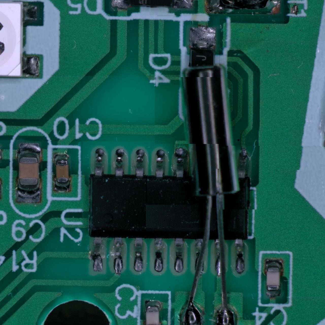
MIST does not blend between pictures, but that's the least of our worries. Since MIST's job is to estimate how to best stitch images of flat subject like some biological sample under a microscope slide, it fails whenever parallax is present, as is visible above with the crystal oscillator poking out of the board. Overall the results aren't too bad though and it allowed me to measure the 1.35 degree angle between my camera and the XY stage.
The simpler approach
What if instead of trying to be smart I just assumed the positions stored in the file names are accurate enough to feed into a blending program?
Just write some Python and feed into Multiblend (a vastly superior alternative to Enblend), right?
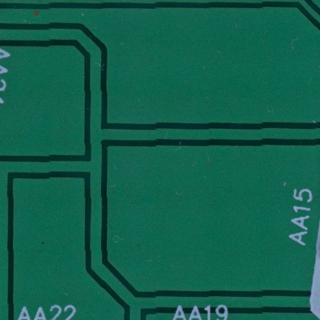
Ah. Since the stage has some angle of 1.35° with reference to the camera, the stitch positions need to all be rotated by that amount in the other direction. Bit o' 2×2 matrix math never hurt anybody. Code here. Slap some board angle correction (different from stage rotation) in GIMP later and you get a beautiful, aligned image.
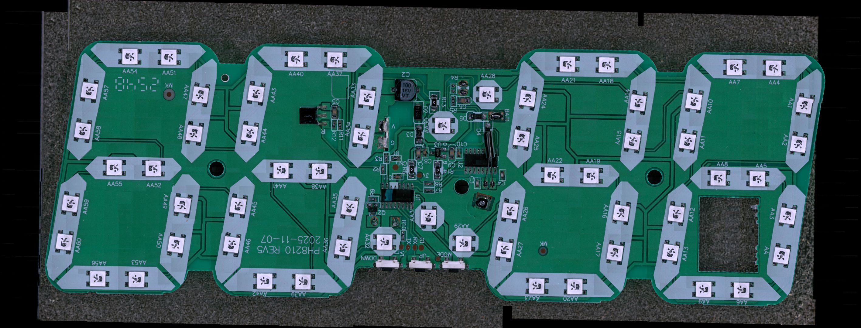
So here, I present to you the biggest, wildest thing ever scanned in high-resolution: a 10€ Lidl (Livarno) LED alarm clock PCB. Though the image on this page is severely downscaled for bandwidth reasons: even compressed as hard as possible in JPEG XL, the size of the original doesn't go below 10 MiB.

It's not perfect. You can see faint vignetting at regular intervals, and there's some slight repeatability issues visible in the long straight traces.
The road ahead
There is still no proper pipeline. A lot of things were done by hand here, and much could be automated:
- Camera-stage angle derived from image movement from a small jog in either X or Y
- Stage backlash and repeatability estimated with back and forth motions
- Stage axis skew computed from the effective movement differences between X and Y for the same distance travelled
- Pixels per millimetre, and consequently zoom level, inferred by just moving the plate at all
- Using a colour calibration chart to compensate for the desaturation visible in the various shots in this article
- Chromatic aberration measurement and correction
- Compensating for vignetting either as a software heuristic or pre-scan calib step using colour targets
- Detecting where the focus plane lies through detecting higher-frequency areas of the images, and subsequently shifting the focus to capture a blur-less 3D image
- And so much more
- And I only have so much attention span
LibrePCB was tried and considered but is generally not mature enough for my taste, although I like its library management more than KiCAD's.
I decided to go without a solder stencil since only 1 board of each iteration would be made, and 5€ saved is 5€ saved.
And yet, early revisions allowed themselves to extend past the nominal 33 mm height inside those cartridges; I was modelling and 3D printing the case myself anyway so that's a luxury I could afford.
Cheap chinese USB microscope cameras tend to not declare themselves properly in their USB Video Class desriptor block, namely say they can output RGB streams when they can't, sending their YUV data instead. Check out the USB UVC Class Specification section 3 for what can be declared, it's pretty well designed and allows for a very wide variety of data and processing layouts.
Inkjet is such a scam technology, yet the microfluidics involved are fascinating. Might have a hyperfocus and write up a blurb on that one day.
Me? Straight? Never.
Plugin that I decided against using for now, preferring to figure out how to best implement the techniques manually first. I got things nailed down for sketching up constraints to make counterbore bridges, but still need some practise for teardrops.
They've been... trying to migrate to an INI config file the build system converts into the equivalent C preprocessor options, with barely any end-user experience improvement in my experience. Honestly their system should've used Kconfig from the get go; it translates to defines, self-documents, can express inter-option conditions, and has both terminal and graphical interface options.
cpfind --linearmatch, as otherwise all image pairs get attempted matches, an O(n²) process that will produce many bad control points due to a PCB's visually repetitive nature.
You know. The one you can purchase standard reference chocolate from.
Franklky ImageJ is such a broken piece of image processing software, and science people desperately try to delude themselves into thinking it's worth keeping around. At least the MIST-specific configuration dialog is understandable, but be wary of the "Preview" button, for it is a misnomer. It will start a non-overlapping image collage process that will run for 4x as long as doing actual stitching.